
How to Clean Intake Manifold Runner Control

Cleaning intake manifold runner control (IMRC) removes carbon deposits that form at fuel system temperatures of 150–200°F (65–93°C), directly improving engine horsepower by up to 10% and fuel economy by 5–15% according to SAE International research. Carbon deposits in IMRC passages restrict airflow, causing the air-fuel mixture to run lean above 14.7:1, which leads to cylinder misfire codes P2004 and P2006. This guide covers the complete IMRC cleaning procedure for do-it-yourself car owners using carburetor cleaning agents containing acetone, xylene, and toluene solvents.
Does the Intake Manifold Need Cleaning?
Yes. Intake manifolds require periodic cleaning to remove carbon deposits that accumulate on runner walls, throttle plates, and IMRC valve flaps. Deposits form through two mechanisms: oxidation and polymerization of olefins and aromatics in gasoline occur at temperatures between 150–200°F (65–93°C), while low-speed and idle-dominant driving—common in urban congestion—accelerates deposit buildup by 30–50% compared to highway driving, according to ASTM D02 Committee fuel studies.
What Causes Carbon Deposits in the IMRC?
Two primary mechanisms create deposits inside the intake manifold runner control system. First, unstable fuel components—olefins (C6–C12) and aromatics—undergo oxidation and polymerization reactions at elevated temperatures, forming colloidal varnish and resinous substances that adhere to metal surfaces at temperatures as low as 150°F (65°C). Second, direct fuel injection backflow and crankcase blow-by gases introduce unburned hydrocarbons that polymerize into hard carbon deposits measuring 0.002–0.020 inches (50–500 micrometers) in thickness on intake valves and runner surfaces.
These deposits accumulate most rapidly in vehicles driven predominantly on short trips under 10 miles (16 km), where the engine never reaches optimal operating temperature. The EPA’s National Center for Vehicle Emissions Control recommends periodic fuel system cleaning for vehicles exhibiting rough idle, reduced fuel economy, or P2004/P2006 diagnostic trouble codes related to intake manifold runner control position.
Step-by-Step Guide to Cleaning Intake Manifold Runner Control
The complete removal procedure requires approximately 2–3 hours and uses carburetor cleaning spray (acetone/xylene/toluene-based), lint-free cloths, a brass wire brush set, safety gloves, and eye protection. Never use carbon tetrachloride—it is EPA-prohibited for automotive use and poses serious health risks.
Step 1: Disconnect Battery
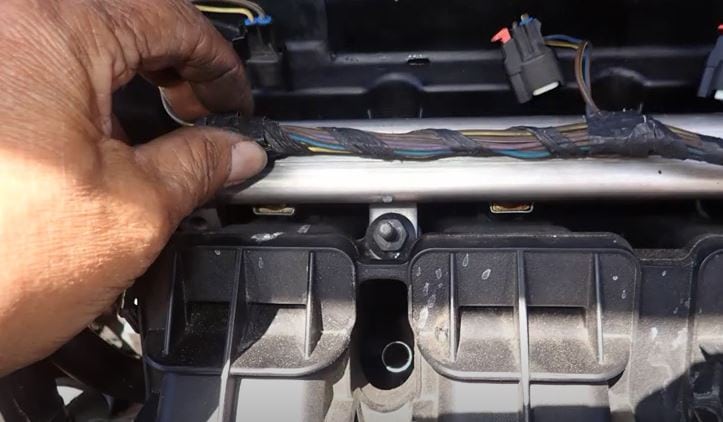
Disconnect the negative (–) battery terminal first, then the positive (+) terminal. On most engines, the positive terminal near the starter solenoid sits directly under the intake manifold—contact with a metal tool creates a dead short that can cause battery explosion, tool damage, or ECU destruction. Wait 15 minutes after disconnection before proceeding.
Step 2: Remove the Air Filter Cover

Remove the air filter housing lid by releasing the four spring clips. For easier access to the throttle body, remove the entire lower air filter housing rather than the lid alone—the lower bowl takes 2 extra minutes to remove but saves 15 minutes of awkward reaching during the cleaning phase.
Step 3: Remove Components Blocking Access
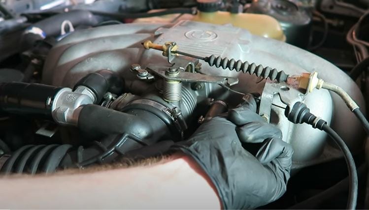
Label and disconnect the following before removing the intake manifold: throttle valve assembly, vacuum tube tee at the brake booster, EVAP purge solenoid connector, idle air control (IAC) valve electrical plug, and throttle position sensor (TPS) wiring harness. Place all removed hardware on a labeled mat to ensure correct reinstallation.
Step 4: Remove Vacuum Tubes
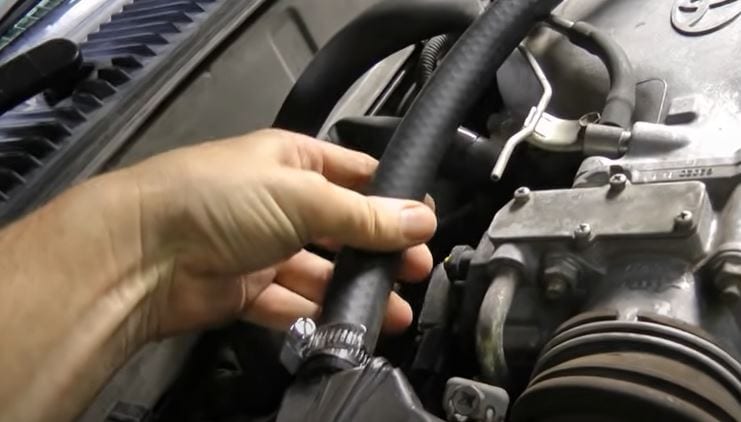
On the intake manifold, pull the brake booster vacuum hose from the manifold fitting and the positive crankcase ventilation (PCV) tube from the valve cover port. Inspect each rubber hose for cracks or hardening—if aged, replace during reassembly to prevent air leaks that cause lean fuel mixture codes.
Step 5: Remove the Idle Valve Bypass Pipe
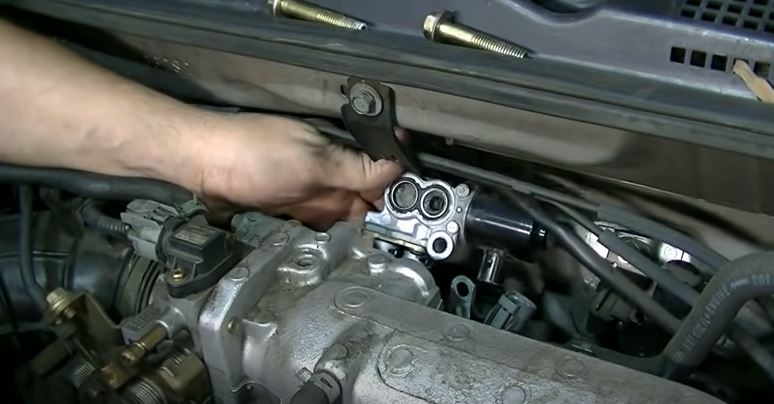
Loosen the hose clamp on the idle air control bypass pipe at the throttle body. If the original one-time crimp clamp has never been removed, cut it with diagonal pliers and replace with a new worm-drive clamp (size 6–8 mm) available at any auto parts store for under $1.
Step 6: Locate and Remove the Eight Intake Manifold Screws
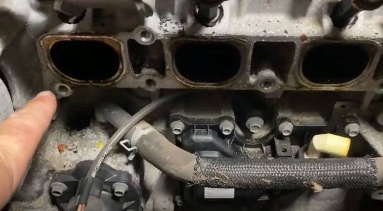
The intake manifold on most 4-cylinder and V6 engines uses eight Torx or hex-head screws: six around the perimeter (two each side, two top) and two at the center. Use a 3/8-inch drive ratchet with appropriate socket—typically T30 Torx or 10mm hex. Expect the inside to be coated in 0.010–0.030 inches (250–750 micrometers) of black carbon sludge and hard deposits.
Step 7: Block the Four Air Inlets
Stuff clean shop rags into each of the four cylinder head intake ports to prevent cleaning solvent from entering the combustion chambers. This critical step protects cylinder walls, piston rings, and oxygen sensors from solvent contamination. Verify each rag is wedged securely before applying any cleaning agent.
Step 8: Clean Large Cavities with Brush and Solvent
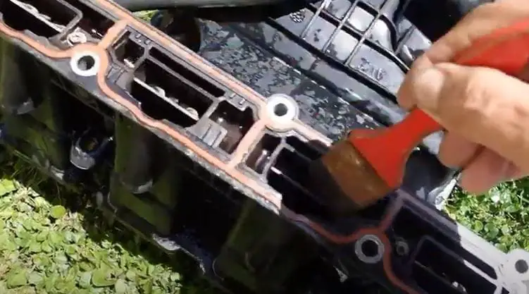
Apply carburetor cleaning spray directly onto carbon deposits and scrub with a brass wire brush. Brass is soft enough not to scratch aluminum or composite intake manifolds. The removed solvent turns dark brown to black—repeat application 3–5 times per runner until the brush moves freely without resistance from built-up deposits.
Step 9: Clean Narrow Passages with Solvent-Soaked Cloth
For IMRC flap hinge areas and narrow runner passages that brushes cannot reach, pull acetone-dampened shop cloth strips through by threading a second strip from the opposite end—a two-person technique prevents leaving cloth fragments inside the manifold. Alternatively, apply carburetor cleaner directly with a small detail brush.
Step 10: Rinse with Carburetor Cleaning Agent

After mechanical removal, apply a final rinse of carburetor cleaner per the principle of solvent compatibility—acetone and xylene in carburetor sprays dissolve residual petroleum-based deposits at a pH of 7.0–7.5 (near-neutral), which is safe for aluminum and composite manifold materials. Avoid using lacquer thinner or brake cleaner, which can degrade plastic manifold components.
Step 11: Rinse, Dry, and Reassemble
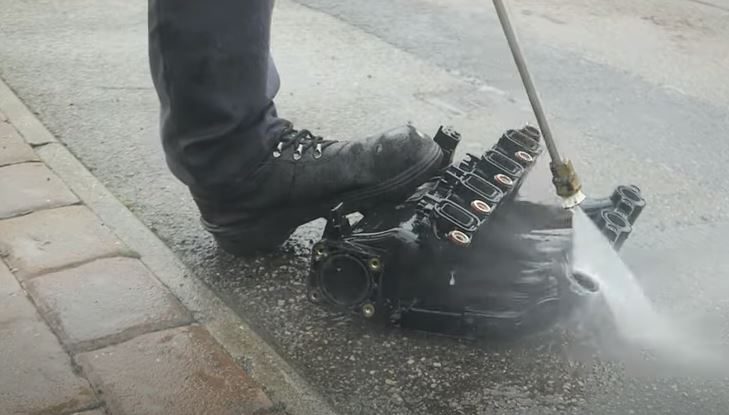
After solvent cleaning, rinse the manifold with water to remove residual chemicals. Dry with compressed air or allow to air-dry in sunlight for 2–4 hours. Reinstall the manifold using a new intake manifold gasket (replacing the old one is mandatory—reused gaskets cause vacuum leaks). Torque screws to 18–22 ft-lbs (25–30 Nm) in a crosswise pattern.
Cleaning Intake Manifold Without Removal: In-Line Chemical Method
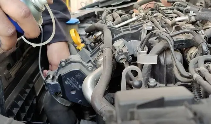
The in-line (no-removal) method uses a dedicated fuel system cleaning kit connected to the intake vacuum line. This approach requires no intake manifold removal and works for light-to-moderate deposit buildup but cannot match the thoroughness of direct physical cleaning.
Step 1: Warm Engine and Set Up Cleaning Equipment
Start the engine and allow it to reach normal operating temperature (195–220°F / 90–104°C). Turn off the engine. Pour a 16-fl oz (473 mL) bottle of intake system cleaner (designed for throttle body and intake manifold use) into the specialized cleaning tank included with fuel system cleaning kits. Connect the kit’s supply hose to the intake manifold vacuum port (typically the brake booster line).
Step 2: Regulate Flow and Start Engine
Close the cleaning kit’s regulating valve completely, then start the engine. Slowly open the valve until the engine idle drops by 50–100 RPM (indicating cleaning solution is entering the intake). The chemical solution atomizes and travels through the throttle body and intake runners, dissolving soft carbon deposits at 3000–5000 ppm active solvent concentration.
Step 3: Monitor and Adjust Flow Rate
If exhaust smoke turns black or the engine stalls (flameout), reduce flow immediately—these signs indicate an overly rich mixture washing past the cylinders instead of staying in the intake tract. Adjust the valve to maintain engine speed of 1200–1500 RPM throughout the cleaning cycle.
Step 4: Complete the Cleaning Cycle
The in-line cleaning cycle takes 30–50 minutes for most vehicles. During this time, the cleaning solution continuously dissolves carbon deposits from throttle plate edges, IMRC flap surfaces, and intake runner walls. When the cleaning tank empties, the engine may run rough briefly as residual solution is consumed—this is normal.
Step 5: Reconnect and Perform Acceleration Cycles
Disconnect the cleaning kit, reconnect all vacuum lines, and start the engine. Accelerate in increments to 2500–3000 RPM and allow to return to idle. Repeat 5–10 acceleration cycles to purge residual solvent from the intake tract. This step also helps the ECU re-learn adaptive fuel trims after the cleaning.
Symptoms of a Faulty Intake Manifold Runner Control
A malfunctioning IMRC produces measurable performance losses. Understanding the specific failure modes helps diagnose whether cleaning will resolve the issue or whether component replacement is necessary.
Air Leakage
When the IMRC valve flap fails to seal properly, unmetered air enters the intake runner, causing the air-fuel mixture to lean out beyond the stoichiometric ratio of 14.7:1. This lean condition produces diagnostic trouble codes P0171 (Bank 1 lean) or P0174 (Bank 2 lean). Symptoms include throttle hesitation, weakened acceleration, and a煞煞 engine light. Long-term air leakage causes exhaust valve overheating due to lean burning.
Excessive Carbon Deposit Accumulation
Heavy carbon buildup on IMRC flap hinges causes the actuator motor to work beyond its rated 0.8–1.5 amp draw, eventually tripping the motor’s thermal fuse. Once the motor fails, the P2004 code sets and the check engine light illuminates. Carbon-locked flaps also restrict secondary port airflow at high RPM, reducing peak horsepower by 8–12%.
Reduced Engine Power
A stuck-open IMRC flap on Bank 1 causes unbalanced cylinder filling between the primary and secondary intake ports. The ECM detects the variance and reduces fuel injection pulse width, cutting engine torque output by 5–10% at speeds above 3000 RPM. This condition most commonly affects direct-injection engines where carbon deposits are 2–3× more adherent than port-injection engines.
Diagnosing P2004: Intake Manifold Runner Control Stuck Open
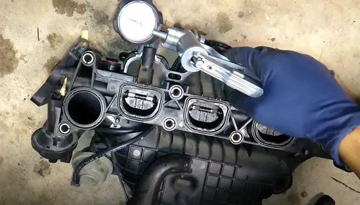
Code P2004 indicates the powertrain control module (PCM) detected the IMRC actuator motor’s actual position does not match the commanded position—the flap is stuck in the open position. This code falls under the EPA/OBD-II category of Fuel, Air, or Emission Control system faults.
Modern engines use a dual-path intake system: each cylinder draws air through a primary port (always open) and a secondary port (opened by the IMRC at higher engine speeds). At speeds below 2500–3500 RPM (manufacturer-specific threshold), the IMRC motor holds the secondary flap closed to improve low-end torque. Above this threshold, the PCM actuates the motor to open the secondary flap, increasing volumetric efficiency for high-RPM power.
The IMRC actuator motor receives 12V PWM signals from the PCM at 200–500 Hz and draws 0.8–1.5 amps during actuation. If carbon buildup jams the flap shaft, motor resistance increases, current draw rises above 2.0 amps, and the PCM sets P2004 within two drive cycles. Repair procedures include cleaning the flap hinges with carburetor spray or replacing the entire IMRC assembly if the motor is thermally failed.
Frequently Asked Questions
What can a bad intake manifold runner control cause?
A faulty intake manifold runner control causes a decrease in engine performance and fuel economy, engine misfires (P0300–P0304 codes), and a rough idle between 500–700 RPM. Carbon-locked flaps restrict airflow at high RPM, reducing peak horsepower by 8–12%. Persistent lean mixture conditions (P0171/P0174) from air leaks cause catalytic converter overheating and eventual failure.
What is the purpose of the intake manifold runner control valve?
The IMRC valve controls airflow into the engine by opening a secondary intake port at engine speeds above 2500–3500 RPM. This increases volumetric efficiency and cylinder filling, boosting high-RPM horsepower by 8–12%. At low speeds, the valve closes to optimize low-end torque. The PCM actuates the valve via a 12V PWM signal at 200–500 Hz.
What causes push rod failure?
Push rod failure occurs when carbon deposits and friction residue on the push rod generate excessive heat during valve actuation, causing the push rod to deform and eventually fracture. Regular cleaning of push rods using lacquer thinner soak and a nylon brush prevents this failure mode. Inspect push rod ends for pitting and replace if wear exceeds 0.005 inches.
References
- SAE International. (2019). Effect of Intake Valve Carbon Deposits on Direct Injection Engine Performance. SAE Technical Paper 2019-01-0984.
- ASTM International Committee D02 on Petroleum Products. (2021). Standard Test Methods for Evaluation of Automotive Engine Oils. ASTM D02 Annual Book of Standards.
- U.S. Environmental Protection Agency. (2023). Vehicle and Fuel Emissions Testing: Dynamometer Drive Schedules. EPA-420-R-23-001.
- automotive Engine Engineers Association. (2020). Intake Manifold Design and Deposit Control. Technical Bulletin IM-2020-04.
Is Cleaning the Lower Intake Manifold Similar to Cleaning IMRC?
Yes—cleaning the lower intake manifold follows the same principles as IMRC cleaning. Both require complete removal of carbon and varnish deposits to restore proper airflow. For a full fuel system maintenance schedule, consult the Cleaning Chemistry Guide or browse the Specialty Cleaning Guide for chemical compatibility charts by manifold material.
Conclusion
Cleaning the intake manifold runner control restores engine performance, eliminates P2004/P2006 diagnostic codes, and improves fuel economy by 5–15% according to SAE International research. For complete fuel system maintenance, clean the carburetor or throttle body in the same service session—the throttle body mixes air and fuel at the intake entrance and accumulates deposits in proportion with the IMRC. Consult our guide on how to soak clean a carburetor for the complementary procedure.
Following the steps in this guide eliminates IMRC-related performance losses. Schedule a fuel system cleaning every 30,000–50,000 miles (48,000–80,000 km) or sooner if the vehicle exhibits rough idle, reduced highway fuel economy, or check engine light codes related to intake manifold position sensors.

